The seismic tomography rig we deploy across Hamilton combines a 48-channel Geometrics Geode seismograph with a 10 kg sledgehammer source and an accelerated weight drop for deeper targets. The 24 geophone spread—planted at 2 to 5 meter intervals depending on resolution needs—captures P-wave and S-wave arrivals that the inversion software processes into a velocity cross-section. Given Hamilton's escarpment geology, where the Lockport Dolomite caprock overlies Rochester Shale, the refraction method picks the overburden-bedrock interface sharply, while reflection tomography images deeper fracture zones within the dolostone itself. On sites along the Niagara Escarpment corridor between Dundas and Stoney Creek, we routinely pair the seismic survey with a resistivity sounding to discriminate between clean fractured limestone and clay-filled solution channels that have very different engineering implications.
A 2D velocity tomogram reveals what a borehole misses: lateral variations in rock quality that change foundation design across the footprint of a single building.
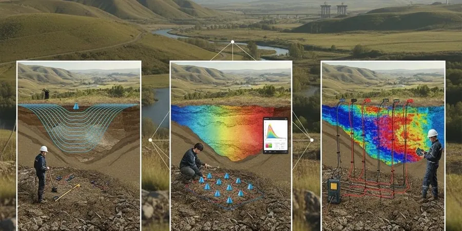
Methodology applied in Hamilton
Typical technical challenges in Hamilton
Under the NBCC 2020, Hamilton falls within a moderate seismic hazard zone, but the real risk on escarpment sites is not shaking amplitude—it is the Site Class contrast between thin soil over bedrock (Class A or B) and adjacent deep valley fill (Class D or E). A single borehole every 30 meters will not capture the transition, and that is where seismic tomography becomes non-negotiable. ASTM D5777-18 requires a minimum of three shot points per spread to constrain the velocity model, and on Hamilton Mountain projects where the Rochester Shale dips gently eastward, we add a reverse shot at both ends to resolve dipping refractors correctly. Ignoring a buried pinnacle of weathered dolostone—common in the Eramosa Member outcrop belt running through the city—can put a foundation half on competent rock and half on soft overburden, creating differential settlement that no amount of structural reinforcement will fix afterward. A velocity tomogram with Vp contours at 0.5 m vertical resolution makes those transitions visible before excavation begins.
Our services
Our Hamilton seismic tomography program covers the full workflow from survey layout to geotechnical interpretation. Each survey is designed around the site's specific question: bedrock depth, rippability, fracture detection, or shear-wave velocity profiling for site class determination.
P-Wave Refraction Tomography
Standard method for bedrock mapping and rippability assessment on Hamilton escarpment sites. We use 24- or 48-channel arrays with hammer and weight-drop sources, processing first-arrival picks through ray-tracing inversion to produce 2D Vp sections with depth penetration typically 15 to 25 percent of spread length.
High-Resolution Reflection Profiling
Applied where overburden is thin and refraction struggles to resolve layering within the bedrock. Our reflection surveys use 14 Hz geophones at 1–2 meter spacing with higher-frequency sources, processed through CMP stacking and migration to image fracture zones, karst cavities, and bedding-plane weaknesses in the Lockport Dolomite.
S-Wave and MASW Integration
For NBCC 2020 Site Class determination (Vs30), we run S-wave refraction or active MASW surveys that yield shear-wave velocity profiles. The output feeds directly into seismic site response analysis and foundation design, particularly for projects in Hamilton's lower city on deep lacustrine clays where Site Class E conditions are common.
Frequently asked questions
What is the difference between seismic refraction and reflection tomography for a Hamilton site?
Refraction maps the velocity structure using first-arrival travel times and works best when velocity increases with depth—ideal for the overburden-over-bedrock condition common on the escarpment. Reflection images velocity contrasts at depth using reflected energy and can resolve layers where velocity decreases, which matters in fractured dolostone or karst zones. On Hamilton Mountain sites with thin drift, we often run both: refraction for the soil-rock interface, reflection for voids and fractures within the caprock.
How deep can seismic tomography see in Hamilton's geology?
Depth penetration depends on spread length and source energy. A 115-meter refraction spread with a weight-drop source typically images to 20–30 meters below grade, sufficient for most foundation investigations. For deeper targets in the lower city—like mapping the Queenston Shale surface beneath 40+ meters of fill—we extend the spread and use higher-energy sources. The Lockport Dolomite transmits seismic energy efficiently, so we often get cleaner, deeper images than in soil-dominated regions.
What does a seismic tomography survey cost for a typical Hamilton project?
For a standard 115-meter refraction line with full processing and a signed report, budget between CA$4,170 and CA$6,250 depending on access conditions, number of shot points, and whether both P-wave and S-wave data are required. Multiple lines on the same site reduce the per-line cost because mobilization is shared. A site walk is always free—we will come out, check access, and give you a fixed-price proposal.
Do I still need boreholes if I run seismic tomography?
Seismic tomography and boreholes answer different questions and work together. The seismic survey gives you continuous 2D coverage between borehole locations, showing lateral changes in rock quality that a point measurement misses. Boreholes provide direct samples for lithology confirmation and laboratory testing. On Hamilton escarpment projects, the best practice is one or two calibration boreholes tied to the seismic line—the velocity model tells you where the transitions are, and the borehole tells you what rock type corresponds to each velocity range.